Project
X15 Power Conversion Board
Designed a stacked power-conversion PCB for Purdue IEEE ROV, converting a nominal 12 V input into regulated 5.2 V/3 A and 3.3 V/1 A rails.
Technologies
Project Files
Overview
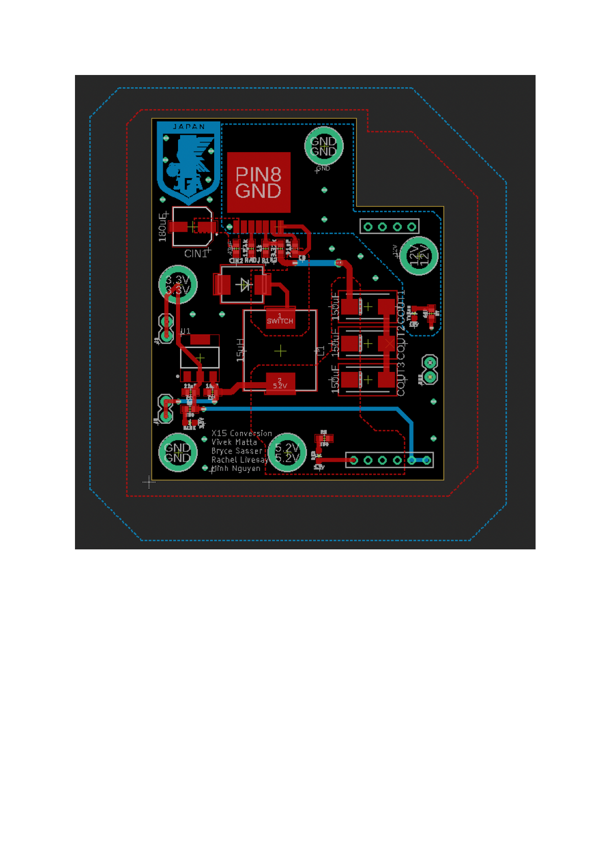
Designed the X15 Power Conversion Board for the Purdue IEEE Remotely Operated Vehicle team. The board stacks above the X15 Power Distribution Board, known as Brickstribution, and converts its nominal 12 V supply into the regulated rails required by the vehicle's Raspberry Pi shield and microcontrollers.
The power architecture uses an LM2679SX-ADJ/NOPB buck converter to generate 5.2 V at up to 3 A, followed by an AZ1117CR-3.3TRG1 linear regulator that supplies 3.3 V at up to 1 A. I used the component datasheets to calculate the feedback and current-limit networks, select supporting capacitors and a Schottky diode, and document the design in the bill of materials.
I replaced unavailable X14-generation components with parts that were in stock, affordable, well documented, and practical for hand assembly. The LM2679's seven-pin TO-263 package reduced external-component complexity and made the converter more approachable to solder than several alternatives considered during research.
Mechanical and electrical integration required coordinating connector locations with the Power Distribution Board designer so both stacked boards aligned correctly. I reduced the board outline, preserved clearance for distribution-board connectors, routed high-current power paths, added ground vias and test points, and incorporated indicators for the 12 V, 5.2 V, and 3.3 V rails.
The project produced a reviewed schematic, calculated component network, bill of materials, and routed PCB revision. The documentation also records design-for-manufacturing improvements for a future revision, including larger test points and labels, increased spacing around small buck-converter components, additional power and ground breakouts, and further board-size reduction.
Project Context
As a member of the Purdue IEEE ROV electrical team, I owned the X15 power-conversion board revision and collaborated with the Power Distribution Board team to integrate it into the vehicle's stacked electrical architecture.
Key Features
- Nominal 12 V input from the X15 Power Distribution Board
- LM2679 adjustable buck stage producing 5.2 V at up to 3 A
- AZ1117 linear-regulator stage producing 3.3 V at up to 1 A
- Stacked-board connector alignment and mechanical-clearance coordination
- High-current routing with ground vias and accessible rail test points
- Visual indicators for the 12 V, 5.2 V, and 3.3 V rails
- Component selection driven by availability, cost, solderability, and datasheet guidance
Challenges
- Replacing out-of-stock components from the previous X14 design
- Aligning stacked connectors while reducing the board outline
- Routing compact high-current power paths around mechanical constraints
- Balancing component density with hand-soldering and test access
- Improving labels, test-point size, and power breakout access for future revisions
Results
- Completed the converter schematic and datasheet-based feedback calculations
- Selected and documented the buck converter, regulator, protection, and filtering components
- Delivered a routed PCB revision aligned with the X15 Power Distribution Board
- Added test points, ground vias, rail indicators, and board-review feedback across iterative revisions
- Produced design documentation and a public repository for manufacturing handoff and future improvement