Project
Embedded PCB Webcam
Co-developed a Wi-Fi webcam that captures JPEG images with an OV2640, transfers them through a SAM4S8B and ESP32, and displays them in a browser.
Technologies
Overview
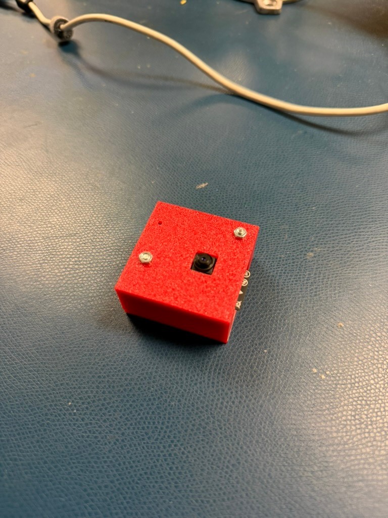
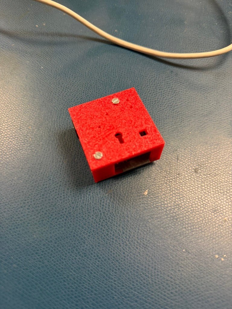
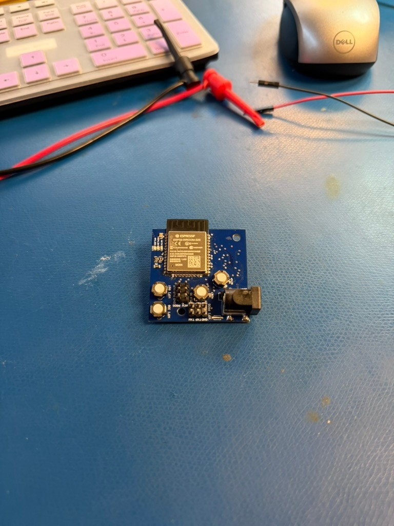
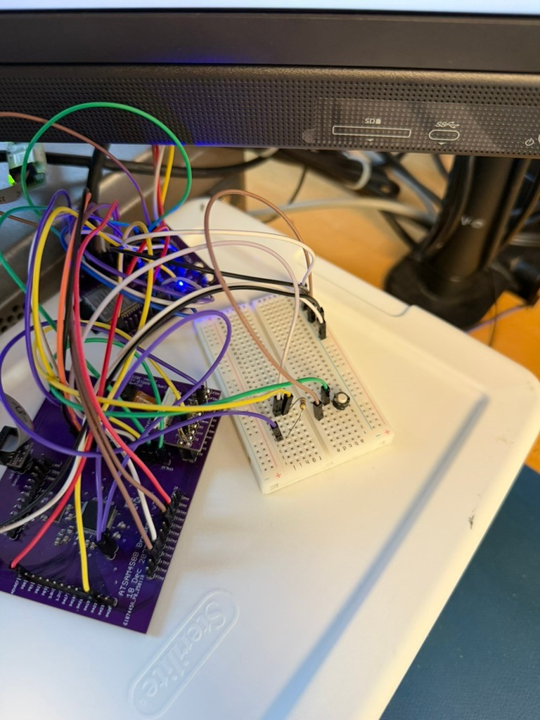
Co-developed an embedded Wi-Fi webcam with Luke de Souza for Northwestern University's CE 326 Electronic System Design course. The project combined a SAM4S8B microcontroller, OV2640 camera module, ESP32-WROOM-32E Wi-Fi module, custom PCB work, embedded C firmware, a browser viewer, and a 3D-printed camera enclosure.
I initially focused on firmware development and then worked across both software and hardware as integration progressed. The firmware was written in C with the Atmel Software Framework and initializes the system clock, GPIO, SPI, UART, Wi-Fi interface, and camera. The OV2640 captures JPEG images, the SAM4S8B transfers image data to the ESP32 over SPI while UART carries commands, and the ESP32 hosts a lightweight web server so a user can view captures from a browser without installing additional software.
The electrical design used KiCad to connect the processor, camera, Wi-Fi module, programming and debug headers, and three regulated power domains: 3.3 V, 2.8 V, and 1.2 V. Early component analysis estimated a $25.09 one-unit core system cost, falling to $19.57 per unit at a quantity of 5,000, and evaluated active, standby, and duty-cycled operation from a 500 mAh battery.
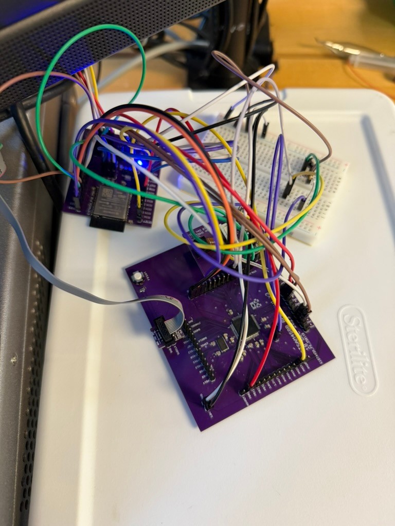
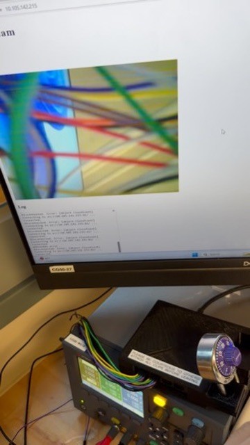
Board bring-up required extensive continuity testing and rework. We removed solder bridges that were blocking camera signals, traced a nonresponsive ESP32 to a Wi-Fi reset pin bridged to ground, and restored programming and terminal output. We also discovered that our manufactured PCB revision omitted the camera-pin connections; after documenting the layout failure, we used a reference PCB provided by the instructor to complete system integration. The final setup successfully captured an image, transferred it through the embedded pipeline, and displayed it in the web interface. A custom 3D-printed enclosure stabilized and protected the camera module for demonstration.
Project Context
This two-person CE 326 project covered the complete embedded-system workflow: component and power analysis, schematic and PCB design, board assembly, C firmware, wired and wireless communication, browser delivery, mechanical packaging, and hands-on hardware debugging.
Key Features
- OV2640 JPEG image capture controlled by a SAM4S8B microcontroller
- SPI image transfer and UART command communication with an ESP32-WROOM-32E
- ESP32-hosted web server for viewing camera output in a standard browser
- Embedded C firmware built with the Atmel Software Framework
- KiCad electrical design with programming, debugging, and external-module connections
- 3.3 V, 2.8 V, and 1.2 V regulated power domains derived from a 5 V input
- One-unit and volume cost analysis plus 500 mAh battery-life estimates
- Custom 3D-printed camera enclosure for alignment and protection
Challenges
- Diagnosing camera initialization failures caused by solder bridges on processor pins
- Discovering that the manufactured PCB revision omitted the camera-pin routes
- Tracing a nonresponsive ESP32 to a Wi-Fi reset signal shorted to ground
- Coordinating camera data, SPI transfers, UART commands, and Wi-Fi delivery
- Scheduling firmware early enough to leave sufficient time for hardware-software debugging
Results
- Captured and displayed camera images through the completed embedded and browser pipeline
- Restored camera operation by locating and removing multiple solder bridges
- Recovered ESP32 terminal output, programming, and Wi-Fi firmware operation after reset-line rework
- Completed system testing with an instructor-provided reference PCB after documenting the custom-board routing error
- Built a protective enclosure and demonstrated a functional end-to-end webcam prototype